Build a Roomba Serial Tether
[originally published 15 Feb 2006 in Makezine blog and edited by Phil Torrone]
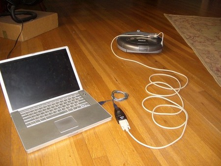
A week ago I got my OSMO//hacker Roomba firmware updater from iRobot. It worked like a charm, giving me a serial port to fully control the Roomba.
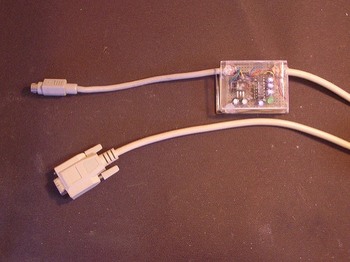
An interface was needed however, since the crazy mini-DIN 7-pin on the Roomba is very unstandard. So the first attempt at a robust interface between a Roomba and a standard PC serial port is my Roomba Serial Interface.
The Roomba Serial Connector
It seems people are confused by the mini-DIN 7-pin connector, citing difficulties in obtaining that specific plug. It turns out that mini-DIN 8-pin plugs will mechanically mate with the 7-pin jacks, with the center key hole in the 7-pin female jack taking the middel pin of the 8-pin plug. Mac high-speed serial cables from the 1990’s work great for this, and I have a ton of those from all my misspent youth doing MIDI on a Mac. So chop up those old Mac serial cables! If you can’t find one, Jameco will sell you one for $3.29.
The PC Serial Connector
Some computers have an RS-232 serial port. Most don’t. To hook this serial interface cable up to your Mac or other modern computer without an RS-232 port, use a Keyspan High Speed USB Serial Adapter. Supported on all platforms and the choice of Mac hardware-hackers worldwide.
Step-by-Step Construction details
The Roomba ROI is a serial interface protocol to let you control your Roomba, but the port on the Roomba doesn’t conform to RS232 standards. This board does the conversion.
There are two boards shown here. The first version (larger, encased in lexan), and the second version (smaller, encased in a blue floss box).

Circuit is simply a 7805 +5V voltage regulator and MAX232 RS-232 transceiver, appropriate capacitors to make it work and a ‘power on’ LED. Because everything needs an LED. Flickr photo with notes here.
Below are parts lists from Jameco (and one from Radio Shack). Jameco doesn’t have the cheapest parts, but they do have an easy-to-use site, ship fast, and carry just about everything that a weekend electronics geek would need. If you want to really scrimp, shop at Digikey or Mouser, and you’ll probably save a few bucks on these parts.
Parts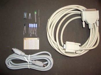
Flickr photo with notes here.
Parts list (from Jameco):
– 1 x Mac mini-din 8-pin cable ($3.29)
– 1 x serial cable with DB9 9-pin female connector ($3.95)
– 1 x 78L05 +5VDC voltage regulator ($0.27)
– 1 x MAX232 RS-232 transceiver ($2.19)
– 1 x green LED ($0.20)
– 1 x 220 ohm resistor ($1.00 for 100)
– 6 x 1 uF electrolytic capacitor ($1.20 for 10)
And from Radio Shack:
– 1 x prototyping pc board ($1.79)
Luckily I had all these parts in my part drawer, so the actual cost for me was zero. If you’ve ever done any little projects, you probably have some of these parts laying around too.
Tools needed
Flickr photo with notes here.
Cutting the cable
Strip off the big plastic cover, then strip off about 1/4″ from all the wires inside. Then do a continuity test on each wire to figure out which colored wire goes to which pin on the jack. Each cable I’ve done has had a different color-to-pin mapping.
Circuit diagram

Larger version here.
Putting the components on the prototyping board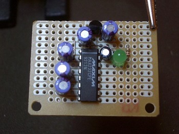
Cut the prototyping board in two, since only half the space is needed.
Place the chip so it straddles the two big verticle bus lines, then start placing parts around it , using the connected pads to minimize the amount of wiring needed. Of course, a few wires are always needed. For that use snipped leads from parts.
Also, create test points using snipped leads to check voltages.
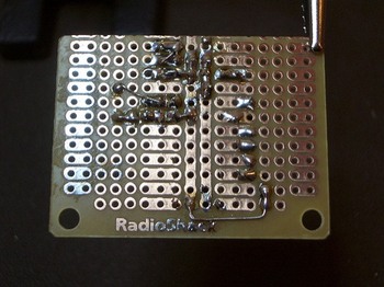
It’s really handy to have the vertical bus lines and the three pads joined. This board is like the best thing Radio Shack sells. :)

Wire up the cables as shown in the schematic and the pin-to-cable color diagram made for the particular cable, solder them down, and hot-glue the cables to the board for strain relief. Flickr photo with notes here.
Testing the voltage
After all the parts are soldered, use the +9VDC wall wart power supply to power up the circuit, and check voltages. The LED should light up and +5VDC should be coming out of the regulator.

The LED lighting up means the interface is getting voltage from the Roomba.
The enclosure is a floss container. Consumer products have a lot of interesting plastic enclosure styles, and so cheap! This one was something like $2.49. A little time with the diagonal cutters and soldering iron allowed the board to fit.
Once it’s in the enclosure, hook up the +9VDC wall wart again and measure voltages on every pin on each cable, to make sure the circuit doesn’t fry the Roomba or the computer’s serial interface.

Get the Software
Now drive your Roomba around like a little tank and play music on it!
35 comments
Here’s a link to a website where you can actually get a 7 pin mini-din cable for $8.55.
http://stockcable.com/minidin.shtml
Fry’s stores (see frys.com for location)
sells a DIN-8-MINI connector for soldering for $1.29
Also a USB “data cable” for Sanyo from futuredial (part#CSAYM02-03 for models 5000,5150,6000,6200,6400) costs only $10, instead of $30 for the Nokia version!
The Sanyo pin-out for the connector (as seen on phone)
1 18
[O=:::::::::]
11 RX (yello in the futuredial data-cable I used)
13 TX (blue)
6,10,16,17,18 GND (brown and black)
—
jpa
Where on hacking roomba website can I find the RoombaComm test program? Will it work on win 98 se?
Hi Paul,
You can find it in the Code section of the website, specficially, the RoombaComm section.
Tod, any chance of an updated Parts and Tools list – many of the provided Jameco part numbers are no longer valid. It would be amazingly useful to just have a list of URLs to click in order to get started, vs. having to comb through long lists on Jameco’s site, trying to find substitutes – especially for some of the less-familiar parts. Thanks :)
Hi Robokojo,
It looks like just the 220 ohm resistor and green LED part numbers were outdated at Jameco. I’ve updated the parts list and they all point to valid Jameco parts now.
Thanks for the tip that some of the links had gone stale.
Thanks Tod, any chance of links for the Tools list on p44? e.g. I can’t seem to find the Mini DIN socket or IC Hooks? Thanks! :)
Yeah both of those I’ve had for over a decade. It looks like the “Mini clip test leads” are a good match for what I use.
The Mini DIN-8 socket I pulled out of an old modem I got from a swapmeet for $1. Sparkfun sells a “MiniDIN 7-pin socket” specifically for Roomba hacking. It’s a better fit than the Mini DIN-8 stuff.
To figure out which tools to use to build circuits, one of the best resources out there is Lady Ada’s “How to Equip Your EE Lab“. She gives lots of good advice about what to start with, what to move up to, and why each tool is useful.
Brilliant – thanks!!! :)
Sorry if I’m off topic but I’ve been searching high and low for such a gadget as the “roostick”. Do you guys figure this would work hooking up a 7 pin din cable to a pfaff sewing machine to my computer?
Hi Jane, Sparkfun sells the RooStick and the iRobot Create Serial Cable will do the same job.
Neither of those, nor will any Roomba things, work with your Pfaff sewing machine I’m afraid. It’s just a coincidence they use the same connector.
However, I bet there are other folks like you who want to hack their Pfaff and make it do cool new things. Do a web search for “Pfaff hacking” or similar phrases; you might find someone has written up as a blog post exactly what you want to do. Good luck.
Thank you! Good advice! Actually this site has got me interested in what you are doing! I’ve hit some good sites along these lines as a result and I’m intrigued. LOL I think I’ve got my fingers in too many pies.
Hi, I have your book and have trying to use my computer to connect with my Roomba 550, the roombacomm program works
Everything comes up ok.. but in controlling the Roomba only some of the buttons work or they all start the roomba forward, can’t turn or read sensors.
( lucky the stop button works.)
I am using the Create Robot Serial Cable… maybe that will not work correctly with Roomba 550 ????
Hi Jeff, All reports I’ve seen say that the 550 should work fine with all the Roomba hacking stuff. If you’re using the RoombaComm code, I suggest you get the latest version of the RXTX java serial library, as the one that I have inside the RoombaComm zip is getting old and may be causing you problems (especially if you’re on Mac OS X 10.5) What OS are you on? If you’re on Windows, go to http://roombadevtools.com/ and try the SCITester program as an alternate test tool.
Excellent book and website Tod!
We have had some problems soldering the ‘inexpensive’ 7-pin mini-DIN plugs but found a source of 8-pin to open-ended leads. We got these from a company in the UK called Lindy Electronics. The relevant webpage is .
I have no financial interest in this company.
These pinouts are not the same as those in the “iRobot Roomba Serial Command Interface (SCI) Specification” document. It gives:
1 Vpwr
2 Vpwr
3 Rx
4 Tx
5 DD
6 Gnd
7 Gnd
It also tells is that the diagram is looking into the socket from the outside. The pins numbers given here are, by comparison, back-to-front. What concerns me most, though, is that here, pin 4 is not even used! This pin might be either transmit or receive, depending on which diagram you consider to be back-to-front.
Why? Why would you want to hack a roomba? For program modification? To emulate robotic concepts… What?
For fun… You truly don’t understand what a geek is. Just the satisfaction of knowing you can…
In more serious sense you could use it as a telepresence robot or other things. It is basically a Create without a vacuum but it can’t hold nearly as much weight.
How do you send commands to it.
Like for the Create it says you can do the (136) 9
to make it home (Something like that) but with OSX how would you actually send the command.
[…] Il existe même un bouquin intitulé Hacking Roomba, des vidéos de hack, ou de chat assis dessus, des tutoriels divers comme par exemple pour construire son propre port série pour Roomba… […]
Just an FYI you might want to put the CPE beside MAX232 RS-232 as it was the first thing I was asked when at the store. Apparently there are other ones. Luckily I guess right. The link to Jamco does provide this, however I had only written down what you listed and not the extended info.
Also, this chip can be ordered from Maxim-IC for free as a sample. I didn’t realize that until afterwards, and ended up paying almost $5 at my local hobby shop (at least I dont have to wait for it to ship).
The Schematic at the DB9 pin 5 need to connect to Ground is missing. please confirmed. I already did and if did not have pin 5 to ground it will only send to ROOMBA but no feedback from ROOMBA.
Hi
Great book. Itching to hack my Roombas. In my hurried enthusiasm, I rushed out and bought a Rootooth, and it won’t even pair with any of my computers or Droids. :(
So, I rolled it back to square one to build a simple serial interface, procured the necessary parts, and now I am confused. I am a late-comer, so I read all the errata/comments, and I can’t believe nobody has these questions:
-Pinout orientation for mini-din7/8 is well documented. Pinout orientation for DB-9 not so much. Is it looking at the connector from the connection side or the wire side?
-Discussion of parts in fig 3-6 references a 10uF cap not mentioned in the parts list nor the schematic. Either way you use 6 caps, but which one is the 10uF? Does it even really matter?
-The two 1.0uF caps connected to pins 2 and 6 appear to be polarized backwards (+ to – and vice versa). I hear that electrolytics blow up when hooked up wrong. I’m no Electrical Engineer – am I misunderstanding something here?
I agree that Radio Shack part no. 276-150 is the best thing they sell! 417 wonderful little holes.
-schlem
Just to follow up on my comment: I did some research on the MAX232 chip and it turns out that the chip outputs +/- 8.5 V on pins 2 and 6 respectively. Who knew? In this context, the schematic shows the negative Cap leads connecting to a “more negative” source. My ignorance.
As regards the 10uF cap – the data sheet (for my flavor max232) makes no mention of this, spec’ing 1.0uF caps, but allowing 0.1uF caps as acceptable.
I still can’t believe that I am the only person with these questions. Maybe I know just enough to be dangerous. Maybe other people are better at answering their questions before whining on the comment board.
Thanks for humoring me, regards,
Schlem
With regards to 10uF capacitor, I’m also as confused as Schlem. No mentioning of it in the part list of schematic, but then out of nowhere it comes up in the description in the book. Also I noticed that Mini DIN 8-pin socket is not used anywhere. I guess there was no need to cut perfect good cable? :)
I have a Roomba Discovery 4210 and I’ve purchased the iRobot USB-Serial cable. I’ve downloaded the various processing tools and have them running in GUI test mode on a Lion MacBook. My problem is actual communication with the Roomba: the /dev/cu.KeySerial1 device doesn’t exist on my machine, and I’m not sure which device to point the serial communications to: obviously the cu.Blue* devices aren’t appropriate. Any thoughts?
Hi Israel,
The iRobot USB-Serial cable should come with instructions on how to install drivers for it. Once you install the drivers, the cable will show up as a serial port with the name “/dev/tty.usbserial…” or “/dev/tty.usbmodem…”. It’s this name that will replace the “/dev/cu.KeySerial1” that is in my example.
Hi Bratan, Schlem,
The socket is the socket on the Roomba, which the mini DIN 8-pin cable plugs in to. The 10uF capacitor I reference is C2 or C3 (the ones on the 5V power supply). The actual value can be between 1uF and 100uF. The capacitor values around the MAX232 are correct.
Hello. I built the Roomba serial interface tether as you’ve explained in your book. Echo test worked well. And I pluged the Roomba serial interface tether into the Roomba. I double click RoombaCommTest option and I select the correct port. However, I see in the display †No Roomba. :( Is it turned on? â€
Also I have one warning:
Warning: RXTX Version mismatch
Jar version=RXTX-2.2pro1
native lib Version=RXTX-2.1-7
I installed Java my computer and Roomba model is 4150.
How we can solve this problem? Please help me. Thank you.
Hi Mine,
What model Roomba do you have? The newer ones operate at 115200 instead of 57600 bps.
How did you install RXTX? (The easiest way I’ve found is to steal the one out of the Arduino software) Normally minor RXTX version mismatches aren’t an issue, but I’m not sure i’ve seen a 2.2pro1 before.
Thanks for quick reply,
My Roomba model is 4150. But I don’t think the problem is the baud rate. I have one small favor to ask. Since I don’t have any experience on java programming, I couldn’t understand the explanations on roombacomm completely. I don’t even know what RXTX is. If it isn’t much of a burden, can you tell me exactly which of the three files to download from your site and which application to use in order to control roomba from Windows xp pc and any other software I require to make it work?
Thanks for your help,
Mine
A USB bib for a Freeduino will work with no modification – only three signals are needed TXD, RXD, and GND. For a Turtlebot, you might also want to isolate the unregulated power (16v) and use it to develop a 12v supply for a Kinect. (The Freeduino bib is 1/2 the cost of a RooStick and is basically the same thing.
[…] There is a small catch. iRobot designed the Create with an 8-pin mini-din connector and 0-5v serial port voltages. To connect my Create to my iCop computer, I require an adapter. Fortunately, one can be purchased from iRobot at a reasonable price, or you can make your own. […]
[…] Hacking Roomba ) all Arbeiten.Die serial line is the same as the functionality presented here . The Create-Tether is a bit more aesthetic though. It also contains the data transfer LEDs to let […]